
The panelboard is already on order when someone notices the load worksheet used the connected-load total as the final service demand. The result is a service that may be too large, too small, or unsupported by the documentation the authority having jurisdiction expects. On a commercial job, that mistake reaches far beyond one spreadsheet cell. It can affect the main switchboard, feeders, transformer, utility coordination, voltage performance, and permit approval.
A sound commercial electrical load calculation turns equipment data into a defensible demand figure. It starts with every nameplate, separates continuous and non-continuous loads, applies the correct demand factors, and carries the result through service, feeder, and transformer selection. It also forces hidden loads into the conversation, including makeup-air equipment, kitchen systems, EV charging, heat pumps, UPS equipment, and battery charging.
By the end, you'll have a practical seven-step pipeline: inventory the building, classify loads, total connected VA, apply continuous-load rules, apply demand factors, convert demand to amperage, and verify the distribution equipment against the actual operating conditions. If you're also reviewing ways to reduce building consumption, these energy-saving tips for commercial buildings belong beside the load study, not after equipment has been purchased.
Table of Contents
- Why Commercial Electrical Load Calculation Matters Before You Buy Any Gear
- The Three Load Types That Drive Every Calculation
- Building Your Load Inventory the Right Way
- Applying NEC Demand Factors Step by Step
- From Calculated Demand to Service, Feeders, and Transformers
- Common Pitfalls and Modern Loads That Break the Old Worksheets
- Site Survey Checklist and When to Call a Licensed Electrician
Why Commercial Electrical Load Calculation Matters Before You Buy Any Gear
The service disconnect is on order when the estimator finds an EV charger missing from the worksheet. That late discovery can force a switchgear change, a transformer review, and another utility conversation before the building can start. A sound commercial electrical load calculation keeps those decisions tied to actual equipment data instead of assumptions.
Start with the connected load. Record every nameplate rating, including heating, air-conditioning, ventilation, kitchen, process, receptacle, EV charging, heat-pump, UPS, and battery-charging equipment. Carry the identified loads at 100% before applying permitted demand factors. This gives the calculation a complete base. Demand reductions belong after the full electrical scope is known and the applicable code rules have been selected.
The workflow is a pipeline, not a single total. Inventory the equipment, classify how each load operates, add the connected VA, account for continuous operation where required, apply the appropriate demand factors, convert the result to amperage, then check service, feeders, transformers, and future capacity against site conditions. A building-consumption review using these energy-saving tips for commercial buildings can sit alongside the load study, but it does not replace it.
The consequences show up in the field
A missed rooftop unit can produce nuisance trips during commissioning. An EV charger or heat pump may push a feeder past its expected operating range. Motor starting can dim lights, long feeders can show unacceptable voltage drop, and a transformer can run hotter than the design team allowed. Those problems may lead to revised drawings, equipment changes, another inspection cycle, or construction delay.
The opposite error also costs money. Treating every load as if it operates at maximum output at the same time can produce oversized gear and unnecessary capital spending. Permitted demand factors exist to reflect how commercial loads operate, but they are applied only after the connected-load inventory is complete and defensible.
Practical rule: Do not order service equipment from the connected-load total alone. Use a documented calculated demand, then verify future capacity, operating conditions, and the equipment that will actually be energized.
Submetering matters after the service is sized, particularly in multi-tenant properties. Owners can bill tenants fairly with submetering, identify which tenant loads drive peaks, and see where available capacity is being consumed. Measurement supports operating decisions. It does not replace the code calculation or the field verification.
The Three Load Types That Drive Every Calculation
The same panel can contain loads that behave very differently. A lighting circuit serving an occupied office, a receptacle circuit in a copy room, and a UPS supplying electronic equipment shouldn't be treated as interchangeable entries in a worksheet. Classification affects conductor sizing, demand treatment, neutral planning, and equipment selection.
Continuous loads are expected to operate for three hours or more, and conductors are sized at 125% of the load under the framework described in the verified commercial-load guidance. Typical field examples include open-office LED troffers, parking-lot wall packs controlled by a photocell, exit lighting, and rooftop-unit supply fans that run through occupied periods. The multiplier belongs in the ampacity and overcurrent-protection calculation where the continuous load applies. Don't add it twice if the table or calculation method has already incorporated the adjustment.
Non-continuous loads operate intermittently or aren't expected to run continuously for the qualifying period. Copy-room receptacles, restroom exhaust fans, corridor lighting controlled by occupancy sensors, and occasional plug-in equipment often fall into this practical category. Their connected ratings still belong in the inventory, but they don't receive the continuous-load multiplier because they're installed.
Non-linear loads require a different design conversation
LED drivers, variable-frequency drives, UPS systems, battery chargers, and computer power supplies can draw current in a non-sinusoidal pattern. Those loads may increase harmonic current in the neutral and contribute to transformer heating, even when their real-power demand looks reasonable. A basic worksheet can total their VA, but it may not fully address neutral capacity, transformer suitability, power quality, or derating.
The following comparison keeps the categories separate at the estimating stage:
| Load Type | NEC Treatment | Field Examples |
|---|---|---|
| Continuous | Calculate at 125% where the load is expected to run continuously | Office lighting, exterior lighting, supply fans |
| Non-continuous | Include the connected rating without the continuous multiplier | Copy-room receptacles, restroom exhaust, intermittent equipment |
| Non-linear or harmonic-producing | Include the load and evaluate neutral, transformer, and power-quality effects | LED drivers, VFDs, UPS equipment, electronic power supplies |
A demand factor doesn't erase a harmonic problem. It only changes the assumed simultaneous demand. If the building has a high concentration of electronic loads, the estimator should flag that issue before someone selects a standard transformer or reduces the neutral based only on balanced fundamental current.
Building Your Load Inventory the Right Way
A panel schedule can say “RTU” or “receptacles” while the installed equipment tells a different story. Start with the schedule, then walk the building. Compare each breaker description with equipment in the field, mechanical schedules, lighting plans, and equipment submittals. Build the inventory in volt-amperes, and record voltage and phase for every entry.
Use nameplate data before breaker size. The breaker identifies circuit protection, not necessarily operating demand. Record lighting, receptacles, fixed motors, HVAC, kitchen equipment, process loads, signage, pumps, fans, and specialty systems. For motors and HVAC, capture manufacturer electrical data, available nameplate ratings, and equipment-specific circuit information. If documents conflict, flag the item for field verification instead of averaging the values.
Keep voltage and phase visible
Separate 120/208-volt loads from 277/480-volt loads as you build the schedule. Keep single-phase and three-phase equipment in distinct entries because the amperage conversion depends on system voltage and phase arrangement. If an equipment schedule gives kilowatts, convert to kVA using the actual power factor. Do not treat kW and kVA as interchangeable.
Use this sequence:
- Pull every circuit into the inventory. Include lighting, receptacles, HVAC, motors, kitchen equipment, signage, pumps, fans, and specialty systems.
- Record nameplate VA or convert accurately. Note voltage, phase, power factor, motor data, and manufacturer-provided minimum circuit ampacity.
- Mark continuous loads at the point of entry. Troffers, signage, and equipment expected to operate continuously need the 125% treatment in the applicable conductor and protection calculation.
- Group by panel and system. Add branch-circuit entries by panel, then roll the panels into switchboards and service sections.
- Reserve future capacity explicitly. Give planned EV charging, heat pumps, UPS equipment, or other known additions a dedicated row. Do not leave them for change-order review.
A generic “miscellaneous” line hides risk. A makeup-air heater, kitchen hood, or process load can affect the service decision more than several ordinary receptacle circuits. The tenant build-out electrical services process should use the same inventory discipline because tenant equipment often changes after the base-building schedule is issued.
Check the connected total before reducing it
Before applying demand factors, confirm that the schedule has a defensible connected-load total. Add every listed entry at its recorded rating, check units, and resolve missing data before reducing the result. Keep continuous and non-continuous loads identified so the later demand calculation has a clear starting point.
Use generic NEC principles and the applicable occupancy rules for the next step. This commercial load-calculation guidance highlights two recurring sources of rework, noncoincident HVAC assumptions and special treatment for the largest motor. Verify both against the adopted code edition and AHJ requirements before final equipment selection.
Applying NEC Demand Factors Step by Step
Use a 4,000-square-foot retail strip to test the calculation from inventory through demand. The connected loads are 30 kVA HVAC, 18 kVA lighting, eight general-receptacle circuits at 1.5 kVA each, and 5 kVA signage:
- HVAC: 30 kVA
- Lighting: 18 kVA
- Receptacles: 8 × 1.5 kVA = 12 kVA
- Signage: 5 kVA
- Connected load: 65 kVA
The arithmetic matters. These inputs total 65 kVA, not 53 kVA or roughly 41 kVA. Do not force a worksheet to match a preferred design result. First verify the nameplate data, units, and operating assumptions. Then apply the demand method required by the adopted code edition and the authority having jurisdiction.
Apply each category deliberately
For this illustrative sample, apply lighting at 100% of the first 3 kVA and 35% of the remainder. Apply receptacles at 100% of the first 10 kVA and 50% of the balance. Carry HVAC separately under the applicable commercial rules. A load calculation guide from Sapper HVAC also helps separate building electrical demand from equipment-specific HVAC analysis, but it does not replace the adopted electrical code or AHJ review.
| Load Category | Connected VA | Demand Factor | Demand VA |
|---|---|---|---|
| HVAC | 30,000 VA | 100% in this sample treatment | 30,000 VA |
| Lighting | 18,000 VA | 100% of first 3,000 VA, 35% of remainder | 8,250 VA |
| Receptacles | 12,000 VA | 100% of first 10,000 VA, 50% of remainder | 11,000 VA |
| Signage | 5,000 VA | 100% in this sample treatment | 5,000 VA |
| Total | 65,000 VA | Category-specific | 54,250 VA |
The lighting row is 3,000 VA + 35% of 15,000 VA, which equals 8,250 VA. The receptacle row is 10,000 VA + 50% of 2,000 VA, which equals 11,000 VA. The resulting calculated demand is 54.25 kVA before motor, continuous-load, or equipment-specific adjustments outside this simplified example.
Keep the continuous-load check visible
Suppose the known lighting circuit includes 8 A continuous. Apply 125% to that circuit component, producing 10 A for the continuous portion. Record the adjustment where it belongs, in the conductor and overcurrent-protection calculation. Do not automatically multiply the entire lighting demand row again if the selected NEC method already includes the continuous adjustment. Repeating the factor can oversize equipment and distort the service decision.
HVAC requires the same discipline. Heating and cooling can be treated as noncoincident only when the equipment cannot operate together under the project conditions. If simultaneous operation is possible, retain the concurrent load. Check the occupancy provisions, equipment schedules, adopted code edition, and AHJ interpretation before accepting a demand table.
The worksheet should show three separate checkpoints: connected load, category demand, and required adjustments. That trail lets a reviewer find whether the error came from the inventory, the factor, or the continuous-load treatment. It also leaves room to test newer loads, such as EV charging, heat pumps, and UPS equipment, rather than hiding them inside an unexamined miscellaneous allowance.
From Calculated Demand to Service, Feeders, and Transformers
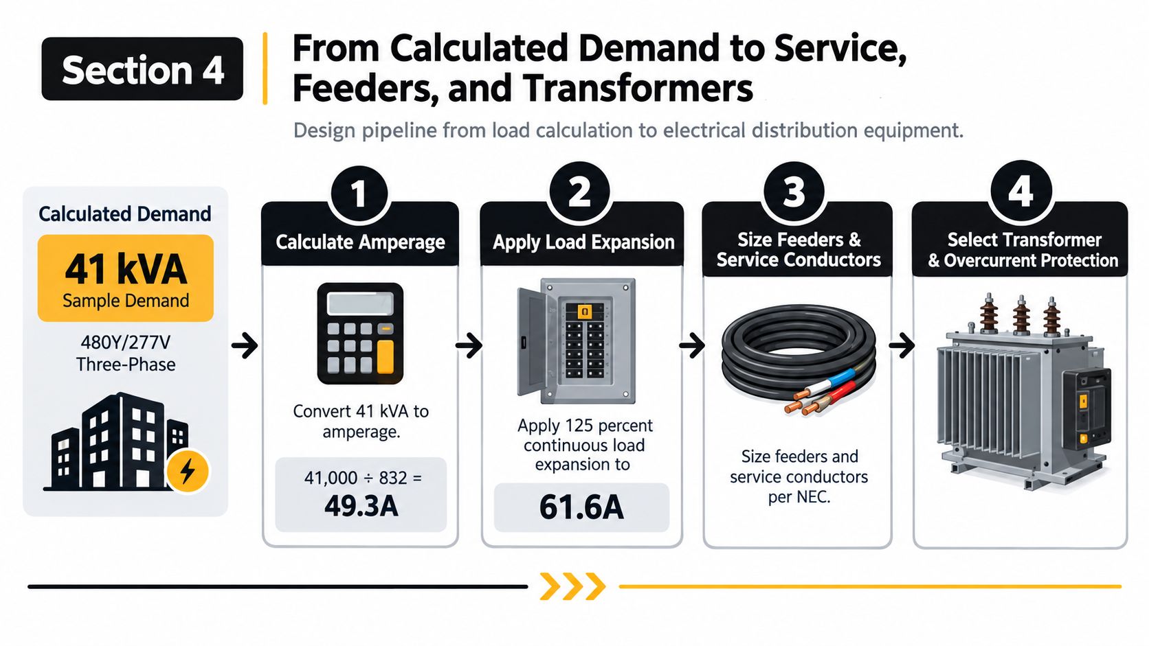
Using the sample's 41 kVA design thread requested for this stage, assume a 480Y/277-volt, three-phase system. The three-phase conversion is:
41,000 VA ÷ 832 = 49.3 A
That establishes the calculated current for the stated demand. The number 832 is the three-phase voltage factor used in this example, based on the line-to-line system voltage and the square-root-of-three relationship.
Carry the continuous load into ampacity
If the full calculated demand is treated as continuous for this simplified design thread, applying 125% gives:
49.3 A × 1.25 = 61.6 A
That doesn't mean every service calculation receives a blanket 125% multiplier. It means the estimator must identify which components are continuous and apply the rule where required. The service and feeder calculation should show the adjustment rather than hiding it in a final rounded number.
From there, select conductors using the applicable ampacity table and installation conditions. The plan calls for checking NEC 310.16 and using the 75°C column for THHN, but conductor size still depends on terminal ratings, ambient conditions, conduit fill, adjustment factors, and the actual load composition. A junior estimator should never select a conductor from ampacity alone without checking the complete installation.
Transformer selection needs more than a kVA label
The sample calls for a 75 kVA transformer, with primary overcurrent protection evaluated under the applicable transformer rules and secondary protection verified against the permitted relationship to transformer full-load current. The requested design checkpoint references 115% supportable demand for primary protection under 450.3(B) and a secondary OCPD not exceeding 125% of transformer FLA. Those figures must be checked against the exact transformer configuration, impedance, conductor protection, and AHJ interpretation.
Voltage drop is the practical field test. A feeder running a long distance can meet ampacity and still deliver poor voltage at the far end, especially when motors start or electronic equipment operates near its limits. A 208-volt service changes the amperage conversion and may require larger conductors for the same kVA, so repeat the entire workflow rather than carrying over the 480-volt result. For projects involving a full three-phase electrical installation, coordinate service voltage, feeder length, transformer location, and utility requirements before final equipment release.
Common Pitfalls and Modern Loads That Break the Old Worksheets
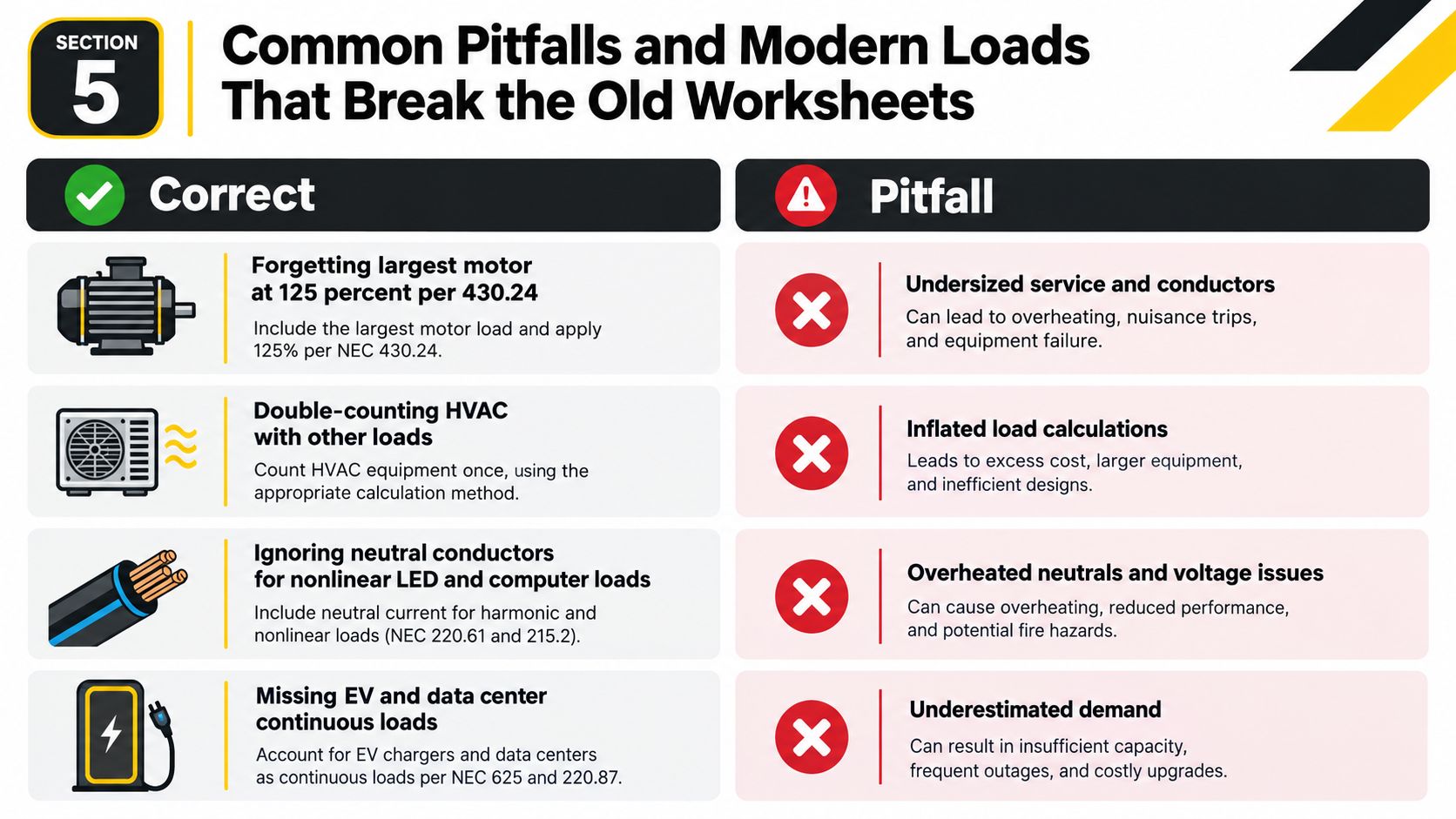
A worksheet can look tidy and still miss the load that fails the design. On a real estimate, the common errors are predictable: the largest motor is absent, HVAC appears twice, electronic loads lack a neutral, or the continuous-load multiplier is applied to a value that already includes it. Every adjustment should show its source and calculation, so another estimator can audit the total.
The largest motor needs separate attention during feeder and service sizing. Treating it like an ordinary branch-circuit load can leave starting performance and conductor sizing wrong. HVAC requires the same discipline. Heating and cooling may be noncoincident, but that assumption must match the controls, equipment sequence, and operating conditions.
The new loads don't fit neatly into old assumptions
Modern projects add operating profiles that a basic occupancy worksheet may understate:
- EV charging: A Level 2 charger can draw 7.7 kW to 19.2 kW. Evaluate the aggregate charging load instead of entering one generic receptacle. Separate maximum possible demand from expected operating draw, and account for duty cycles using recent electrical-load-calculation guidance.
- Heat pumps: Replacing conventional rooftop equipment with heat pumps can materially change electrical demand and increase current for each unit. Treat that as a design possibility, then verify it with equipment submittals rather than an early mechanical allowance.
- UPS and batteries: Include UPS losses, battery charging, lighting, and cooling in high-density facility planning. Cooling can represent 70% to 100% of IT load, and continuous-load planning may require a 25% service-capacity margin, as described in the data-center power-planning reference. These loads need more than an occupancy worksheet.
- Solar and storage interconnection: A new source changes the available-current and equipment-rating review. Check backfeed limits, disconnecting means, and applicable interconnection rules before adding generation to an existing service.
A worksheet built for a simple retail fit-out may no longer represent the building after EV charging, heat-pump conversion, UPS equipment, or battery storage enters the scope.
Nonlinear lighting and computer loads can increase neutral current and transformer heating. Do not reduce the neutral merely because phase loads appear balanced on paper. Recalculate when any of these conditions appears, even if the existing main breaker has not tripped. The connected-load sum is only the starting point. Nameplate inventory, demand factors, operating sequence, and modernization loads must all survive review before circuits or equipment are added.
Site Survey Checklist and When to Call a Licensed Electrician
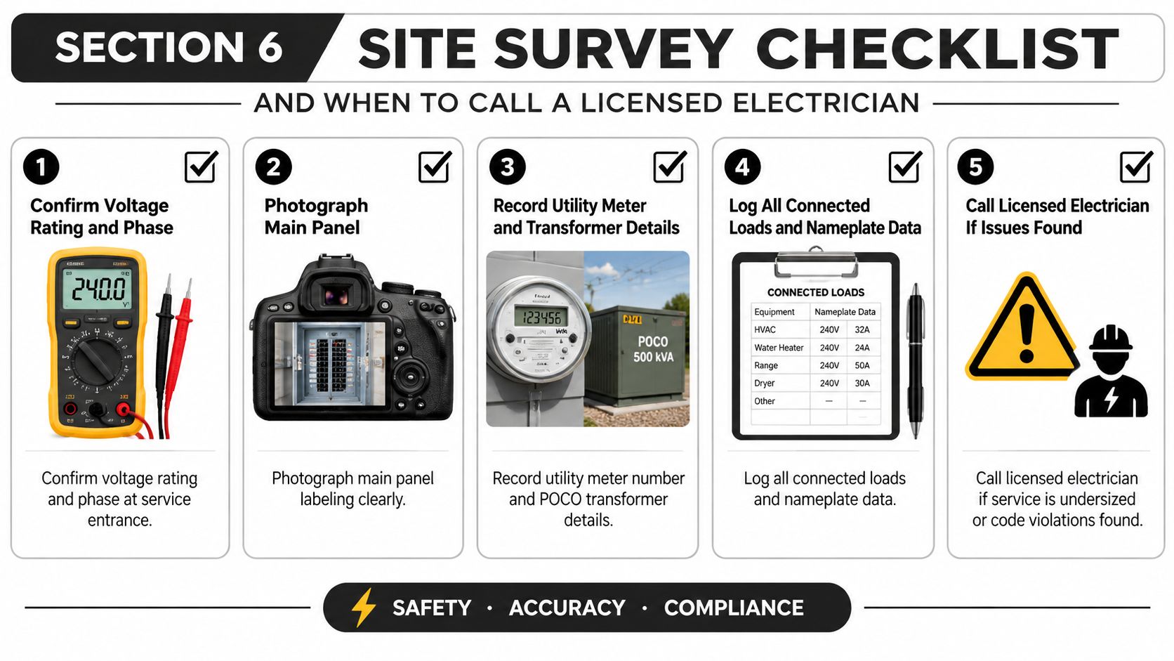
A good survey turns the worksheet into field evidence. Start at the service entrance and verify the voltage rating, phase arrangement, and available equipment information. Photograph the main-panel labeling, record the utility meter and provider-owned transformer details, and compare the panel schedule with what is physically installed.
Walk the site in a fixed order
Use the first hour to capture the facts that most often cause a second visit:
- Confirm voltage and phase: Identify whether the building uses 480Y/277 V or 208Y/120 V, and verify the actual service configuration.
- Photograph identification: Capture the main panel, switchboard labels, feeder tags, transformer nameplate, and any damaged or altered markings.
- Record utility information: Note the meter identification and utility transformer information available at the site.
- Log equipment data: Photograph nameplates for HVAC, motors, kitchen equipment, signage, EV equipment, UPS systems, and battery chargers.
- Measure the route: Record feeder lengths, conductor material, conduit type, routing constraints, and conditions that may affect voltage drop or ampacity.
- Flag fault-current information: Obtain available fault-current data where required and compare equipment ratings with the installation.
- Separate normal and standby systems: Identify optional standby, emergency, and legally required standby equipment before combining loads.
Hand the calculation to a licensed electrician or engineer when the work involves aluminum service conductors, parallel feeder runs, high available fault current, optional standby systems, EV supply equipment, or line-side service work. A maintenance-focused electrical maintenance contractor guide can help organize ongoing inspections, but it doesn't replace project-specific design review.
Three handoff conditions are absolute: permit-required work, services above 600 A or 480 V, and any tenant improvement that changes the service rating. In those cases, the licensed professional should confirm the calculation, equipment ratings, utility requirements, and permit package before installation begins.
Lighthouse Energy Services provides commercial load analysis and electrical distribution planning to help size service equipment, feeders, transformers, and generator capacity from the actual building load. If your project involves a tenant build-out, equipment upgrade, EV charging, or a service change in Palm Beach County, visit Lighthouse Energy Services to discuss the calculation and field verification before ordering gear.