
A boat lift that worked perfectly last season can start tripping its breaker after one heavy South Florida storm. The motor may still be healthy. The failure often begins at a corroded terminal, a wet enclosure, a damaged cable entry, or a bonding connection that no longer provides a dependable path for fault current.
That's why boat lift wiring needs to be designed for more than initial operation. It must handle rain, salt spray, ultraviolet exposure, condensation, flooding, motor starting current, and repeated seasonal use. A compliant installation should protect people near the water, protect the equipment, and remain inspectable after years of coastal exposure.
Table of Contents
- Why Boat Lift Wiring Demands Code-Level Attention
- Preparing Your Boat Lift Wiring Installation
- Wiring a Single-Phase or Three-Phase Boat Lift
- Designing for Corrosion and Long-Term Reliability
- Troubleshooting Common Boat Lift Electrical Problems
- Commissioning and Acceptance Checklist
Why Boat Lift Wiring Demands Code-Level Attention
A recurring trip after a storm is a warning, not an inconvenience to reset. Water may have entered a control box, salt may have formed a conductive path across a termination, or a loose connection may be heating when the lift starts. Replacing the motor without checking the complete circuit can leave the actual fault untouched.
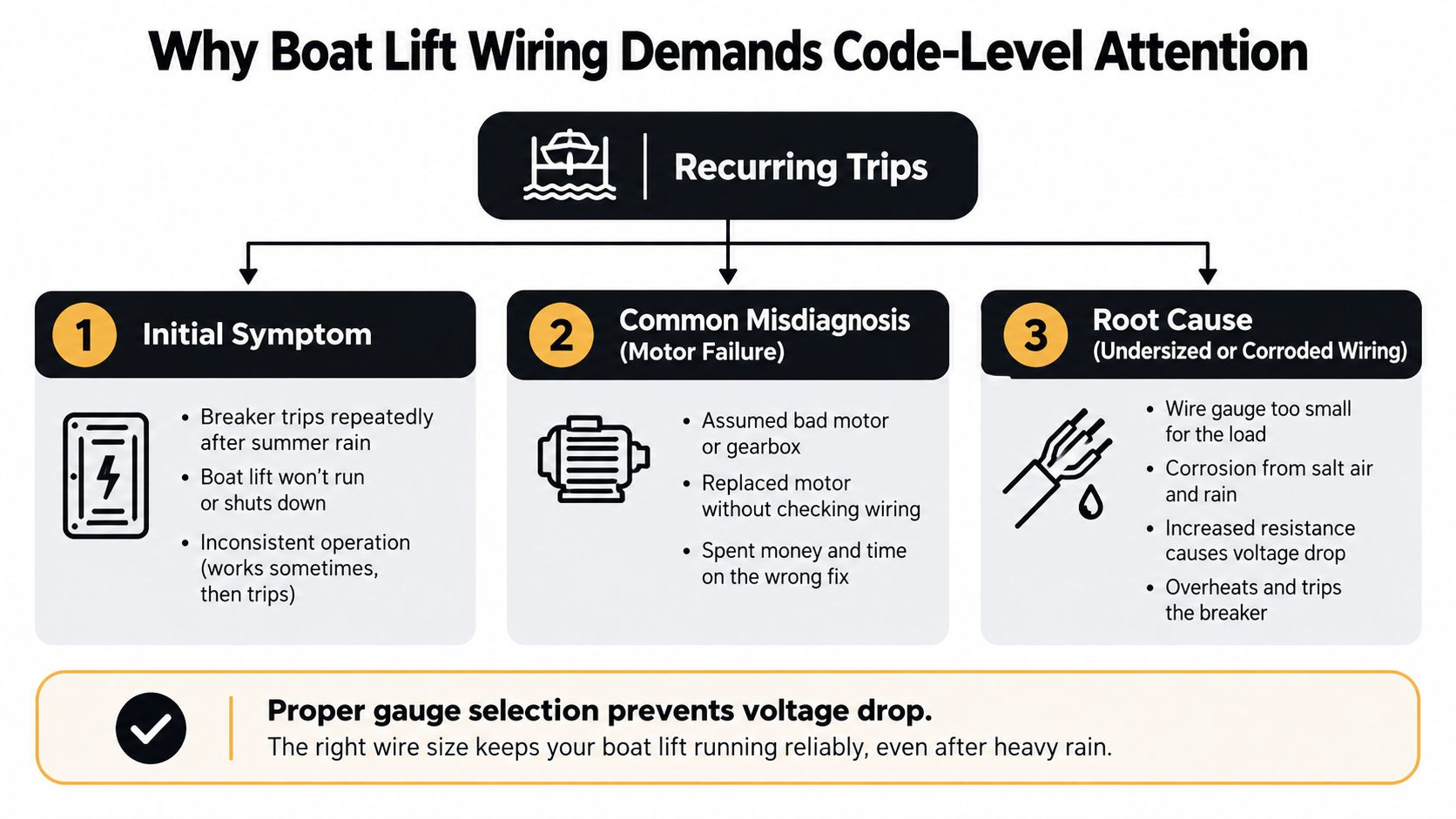
Boat-lift wiring falls under the same dock and marina safety framework used for other electrical equipment near water. Under National Electrical Code Article 555, feeder circuits installed on docking facilities require listed Ground-Fault Protection of Equipment, or GFPE, set to open at no more than 100 milliamperes. Shore-power receptacles require individual ground-fault protection at no more than 30 milliamperes, and those receptacles must be rated at least 30 amperes. The marina electrical-safety guidance from Bender explains why these protections serve different purposes.
The distinction matters. The 30 mA receptacle threshold provides more sensitive protection for personnel, while 100 mA GFPE protects feeders, equipment, and wiring from hazardous leakage. Those limits aren't interchangeable, and installing one device doesn't automatically satisfy every protection requirement in the system.
What the protection is actually guarding against
A boat lift can combine a motor, control station, exposed connections, metal framing, and dock structure in a wet, conductive environment. A damaged conductor or failed component can energize metal parts or allow current to enter surrounding water. That creates an electric-shock-drowning hazard, not merely a nuisance trip or a motor-maintenance problem.
For boat-hoist outlets on docking facilities, NEC Section 555.35(C) requires GFCI protection when the circuit voltage doesn't exceed 240 volts. The correct design still depends on the lift's voltage, amperage, disconnecting means, grounding path, and exposure to rain, spray, saltwater, and flooding.
Practical rule: Never treat the dock frame, metal conduit, or water as the grounding path. A dedicated insulated equipment-grounding conductor must return continuously to the supply panel.
A homeowner can observe a tripping breaker, but diagnosing a dock circuit safely requires testing that may expose live conductors and energized metal. If the lift trips after rain, if someone reports tingling near the dock, or if the installation has unknown grounding or bonding, stop using it and have a qualified electrician inspect the complete circuit.
Preparing Your Boat Lift Wiring Installation
Good installation starts before the first conduit fitting is tightened. The installer needs the lift motor's nameplate, the supply-panel information, the route to the dock, the expected exposure to water, and the manufacturer's wiring and overload requirements.
Start with the motor and panel
Record the motor's voltage, full-load current, phase, and required overload protection. These details determine the branch-circuit conductors, disconnect, controller, and protective devices. The breaker must protect the conductors and work with the motor's starting characteristics. Oversizing it to stop nuisance trips can leave undersized wiring exposed to overheating and can conceal a failing motor or connection.
A sound pre-installation review should answer these questions:
- Motor data: What voltage, phase, full-load current, and overload settings does the manufacturer specify?
- Circuit route: How far is the supply panel from the lift, and where will the conductors pass through wet or exposed areas?
- Disconnect location: Can the disconnect remain readily accessible and within sight of the motor during normal operation and storm cleanup?
- Equipment ratings: Are the boxes, fittings, cable, conduit, disconnect, and control components listed for the locations where they'll be installed?
- Grounding path: Does an insulated equipment-grounding conductor run continuously back to the supply panel?
- Bonding: Are exposed conductive lift and dock components connected with the required supplemental bonding?
- Testing plan: Who will verify insulation, polarity, grounding continuity, protective-device operation, and motor rotation?
For U.S. docking facilities, boat-hoist outlets on circuits not exceeding 240 volts require GFCI protection. Marina feeder ground-fault protection must open at no more than 100 mA. The marina circuit equipment-grounding conductor must be insulated and at least 12 AWG, even where the calculated conductor size would otherwise be smaller. Metal parts likely to become energized require supplemental bonding with solid copper conductor at least 8 AWG. The NEC-focused marine wiring guide from Electrical Construction and Maintenance provides the relevant framework.
Build around the environment
Palm Beach County installations face salt air, spray, intense sun, condensation, and storm-driven water. Use wet-location equipment, minimize splices, keep junction boxes above splash and flood exposure where the site permits, and select corrosion-resistant terminals and strain reliefs.
Conduit choice also affects physical protection and future serviceability. If you're weighing impact resistance against easier handling, this comparison of Schedule 40 vs. 80 conduit is a useful reference before selecting the route and fittings.
A detached dock subpanel should be supplied with a four-wire feeder. Neutral and equipment grounding must remain isolated downstream of the service disconnect, with the final grounding and bonding arrangement verified against the adopted local code and site conditions. The broader dock-power context is covered in this guide to dock power pedestal installation.
Wiring a Single-Phase or Three-Phase Boat Lift
The wiring path looks straightforward on paper. From the supply panel, conductors travel through an appropriate raceway or wet-location wiring method to a disconnect, then to the controller or contactors, and finally to the motor. The difficult part is preserving that protection through every connection exposed to salt, movement, heat, and water.
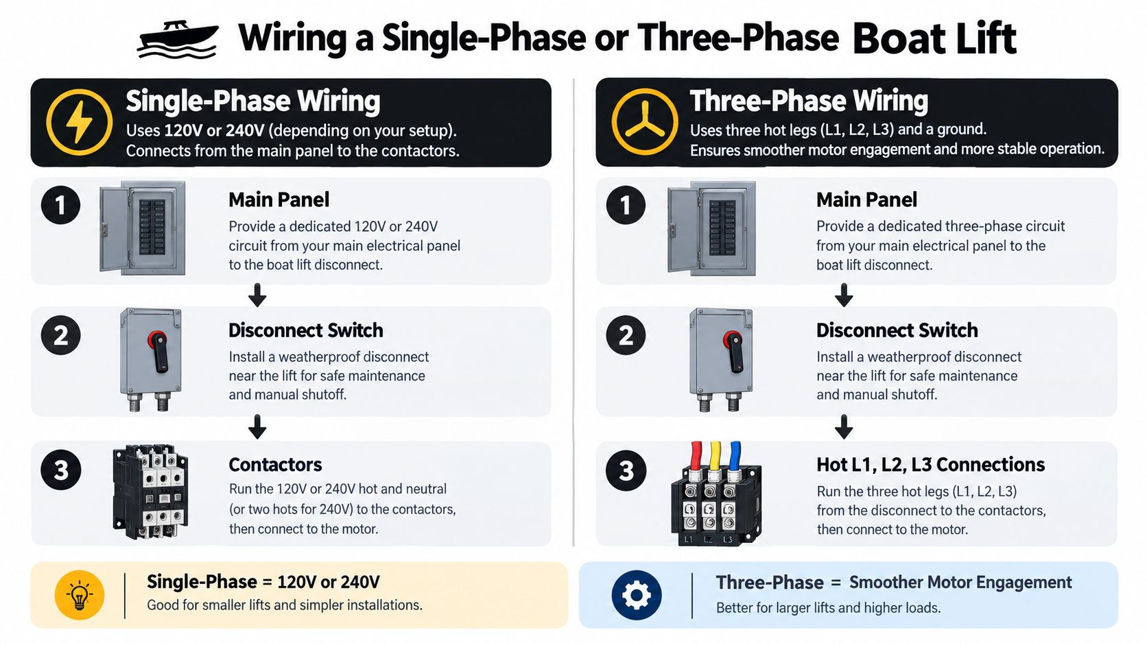
Single-phase arrangements
For a single-phase lift, the narrative wiring diagram is:
Supply panel → protective device → marine-rated raceway or wet-location cable → disconnect → GFCI protection where required → weatherproof junction box or controller → motor overload protection → motor.
The exact conductor size comes from the motor nameplate, circuit length, installation conditions, and applicable code requirements. Long runs deserve particular attention because voltage drop can make a motor start poorly, draw excessive current, or trip protection under load. The installer should measure voltage at the motor while the lift starts and while it raises the boat, not only at the panel with the motor idle.
The disconnect should be readily accessible and within sight of the motor. The motor connection belongs in a listed weatherproof enclosure with fittings that seal the cable entry without crushing or loosening the jacket. Indoor-rated boxes and ordinary cable fittings often fail early when condensation, spray, and ultraviolet exposure reach them.
Bonding is separate from the circuit's equipment-grounding conductor. The motor housing, lift frame, and relevant dock metalwork need dependable bonding connections. A bonding jumper that is loose, undersized, or attached over corrosion can look complete while offering poor fault-current continuity.
Three-phase arrangements
A three-phase lift follows the same physical protection principles, but the power conductors are L1, L2, and L3, along with the equipment-grounding conductor. The controller typically includes contactors, overload protection, and a means of disconnecting the motor circuit. The motor's phase sequence must be verified because incorrect rotation can cause the lift to operate in the wrong direction or create mechanical stress.
A practical diagram is:
Supply panel → three-pole protective device → L1, L2, L3 through the raceway → disconnect → controller and overload relay → motor terminals, with the equipment-grounding conductor bonded to the motor housing and lift structure.
The electrician should jog or test the motor under controlled conditions before full operation, confirm rotation, and correct the phase sequence if necessary. The equipment-grounding conductor still runs continuously back to the supply panel. Three-phase conductors don't make the dock frame an acceptable substitute for that conductor.
Conduit fill, bend radius, physical protection, and cable support deserve attention on exposed runs. Rigid or flexible metal conduit may be appropriate where it's listed for the environment and installed with compatible fittings, while nonmetallic raceway may offer corrosion advantages in some locations. The correct choice depends on exposure, mechanical risk, routing, and local requirements, not on the label “marine-grade” alone.
For a concise explanation of circuit planning fundamentals, this practical circuit design guide can help organize the load, protection, and conductor decisions. Complex three-phase work, controller changes, subpanel grounding, and any circuit exposed to flooding belong with a licensed electrician. Additional context is available in this guide to three-phase electrical installation.
Designing for Corrosion and Long-Term Reliability
A lift can pass its initial inspection and still develop a dangerous defect later. Salt deposits bridge terminals, ultraviolet exposure weakens jackets, condensation collects inside raceways, and dissimilar metals corrode where lugs and conductors meet. Water can also wick along a cable into an enclosure even when the outside entry appears sealed.
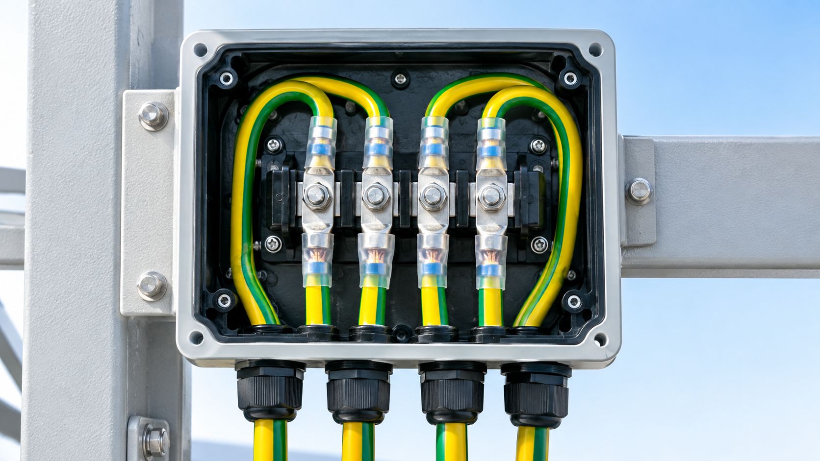
Treat corrosion protection as a system
A corrosion-resistant enclosure can't compensate for poor drainage. A sealed fitting won't fix a loose terminal. A marine-rated cable won't prevent damage where it rubs against sharp metal or hangs under strain.
Reliable installations coordinate several details:
- Enclosures: Choose equipment listed for wet locations and protect it from direct splash where the site allows.
- Cable entries: Use compatible, sealed strain reliefs and avoid downward-facing entries that collect water.
- Splices: Minimize them, document them, and place them where they remain accessible for inspection.
- Metals: Avoid unsuitable dissimilar-metal combinations at terminals, lugs, fasteners, and bonding points.
- Routing: Support exposed wiring, protect it from impact, and limit ultraviolet exposure where practical.
- Drainage: Prevent trapped condensation and give water a path out of equipment spaces where the enclosure design permits.
Marine lifting-appliance guidance emphasizes designing for foreseeable operating conditions and environmental exposure, including temperature effects. It also supports documented wiring diagrams that identify cable size, insulation, operating current, and protective devices. The marine lifting-appliance guidance from Lloyd's Register reinforces why documentation and environmental design should continue beyond the day of installation.
Leave a service record behind
Before concealed terminations disappear behind panels or decking, photograph them. Record conductor sizes, protective-device settings, torque values, bonding points, enclosure types, and circuit labels. The record gives the next electrician a starting point and makes it easier to identify a change after a storm.
Inspect seasonal connections for salt deposits, discoloration, looseness, heat damage, cracked insulation, and corrosion at bonding points. Arrange a professional review at least annually, and inspect sooner after flooding, major storms, unusual tripping, or prolonged heavy use. The right interval depends on exposure, but waiting for the lift to fail under load is a poor maintenance strategy.
A “marine-grade” label raises the system's tolerance for exposure. It doesn't eliminate inspection, cleaning, torque checks, or replacement.
Troubleshooting Common Boat Lift Electrical Problems
A tripping device is reporting a condition, not creating one. Resetting it repeatedly, bypassing GFCI protection, or fitting a larger breaker can turn a visible warning into hidden conductor damage or energized metal.
Start by identifying when the fault occurs. Does the device trip immediately after rain, only when the motor starts, only while raising the boat, or even when the lift is idle? That timing helps separate moisture ingress, starting-current problems, voltage drop, and insulation or bonding faults.
Use the symptom to choose the test
GFCI nuisance trips often point to moisture in an enclosure, damaged insulation, a failing motor, or leakage across contaminated terminals. The electrician should isolate sections of the circuit, inspect entries and covers, test insulation, and verify the protective device with calibrated equipment. A homeowner can keep the circuit off and document the conditions, but shouldn't open energized marine equipment.
Voltage drop under load appears as a slow or weak lift, dimming control indications, motor heating, or tripping during operation. Measure voltage at the motor while starting and lifting. Undersized conductors, excessive run length, loose lugs, and corroded contacts are common causes. Tightening or replacing a visibly loose external connection may seem simple, but de-energizing, torqueing, and verifying the complete circuit is professional work when the connection is part of a dock system.
Bonding gaps and stray current require immediate caution. A voltage reading between exposed metal components can indicate a fault or bonding problem. Don't rely on a casual multimeter reading as proof that the dock is safe. Keep people out of the water and have a qualified electrician test grounding continuity, bonding, insulation, and connected equipment.
Motor-start trips can result from a failing motor, degraded starter contacts, incorrect overload settings, voltage drop, or a protective device that doesn't suit the installation. An oversized breaker isn't a repair. The electrician should compare the protective settings with the manufacturer's instructions and inspect the motor while it starts and operates under load.
| Symptom | Likely cause | Field test | DIY or electrician |
|---|---|---|---|
| Trips after rain | Moisture ingress or contaminated termination | Inspect de-energized enclosures and test insulation | Electrician |
| Trips when lifting | Voltage drop, loose connection, overload, or motor fault | Measure motor voltage during starting and lifting | Electrician |
| Lift runs slowly | Undersized conductors, low voltage, mechanical load, or poor contact | Compare supply and motor voltage under load | Electrician |
| Tingling or unexpected voltage near metal | Bonding or insulation failure | Test continuity, insulation, and fault paths | Electrician immediately |
| GFCI won't reset | Active fault, wet equipment, or failed protective device | Keep circuit off and inspect for water entry | Electrician |
| Visible damaged exterior fitting | UV, impact, or corrosion damage | De-energize and photograph the defect | Electrician if connected to the circuit |
Safe homeowner actions include turning off the circuit, keeping swimmers away, recording when the problem occurs, and checking for obvious storm damage from a safe position. Don't bypass protection, substitute a larger breaker, or continue operating a lift that trips repeatedly.
Commissioning and Acceptance Checklist
Commissioning should prove that the installation is safe under realistic conditions, not merely that the motor turns. The electrician should verify each connection, protection device, grounding path, enclosure, and operating condition before handing the lift back to the owner.
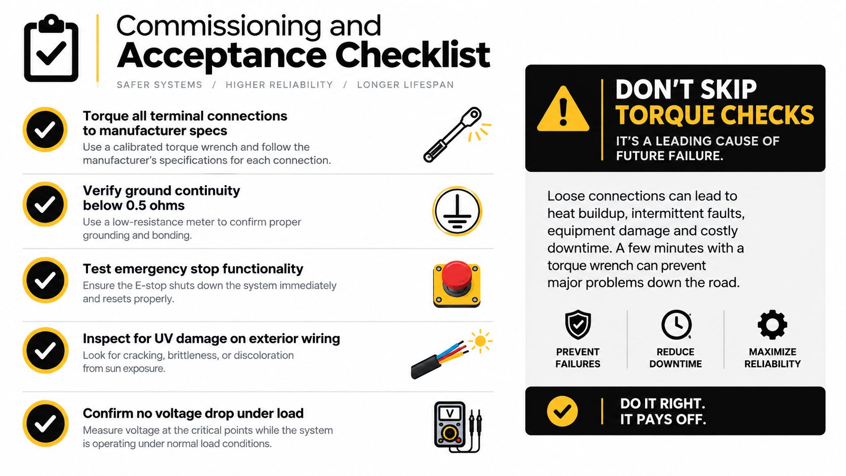
Complete the electrical checks
Use a written record with the circuit identification, test method, result, and person performing the work.
- Torque terminations: Tighten terminals to the manufacturer's specified values and record the results. Loose connections are a common source of heat and intermittent operation.
- Verify grounding continuity: Test from the motor housing, lift frame, and bonded metal components back to the panel.
- Test insulation: Check the feeder and motor circuit for insulation integrity before energizing.
- Test GFCI operation: Use an appropriate tester and document the trip result. Don't rely only on pressing a button without confirming the circuit response.
- Check polarity and phase sequence: Confirm single-phase polarity or three-phase rotation before full operation.
- Measure operating voltage: Test at the motor during startup and while lifting, not just at the idle panel.
- Inspect enclosures: Confirm covers, gaskets, fittings, strain reliefs, and drainage are suitable for the location.
- Verify the disconnect: It must remain readily accessible and within sight of the motor.
- Label the circuit: Identify the voltage, amperage, equipment served, and ground-fault protection at the panel.
- Document concealed work: Retain photographs, diagrams, settings, torque information, and test results.
The image's checklist references a continuity target of below 0.5 ohms, but the acceptance value must be interpreted by the qualified electrician using the test method, conductor length, equipment, and adopted requirements. The same caution applies to any trip-time or insulation result. A number without test conditions doesn't establish a safe installation.
Maintain the protection after commissioning
Electrical safety around a boat lift is fundamentally an electric-shock-drowning concern. The National Marine Manufacturers Association safety guidance advises never swimming in marinas or near vessels connected to shore power, using UL marine-approved shore-power cords, and having a certified marine electrician inspect the boat's complete AC electrical system, including shore-power grounding, at least annually. Marine-facility safety guidance also supports GFCI protection, stray-current checks, and continuity testing.
Schedule the lift review alongside broader seasonal care. A seasonal boat maintenance checklist can help coordinate inspection of the vessel and lift, but electrical testing still requires a qualified person with the right instruments and training. For Palm Beach County properties, specialized marina electrical services in South Florida are appropriate when the work involves a dock subpanel, three-phase equipment, storm damage, flood exposure, or uncertain bonding.
The homeowner can retain documentation, keep the panel and disconnect accessible, observe protective-device operation, and report changes promptly. A licensed electrician should handle energized testing, circuit alterations, grounding and bonding verification, three-phase work, and any repair where water may have entered the system.
Lighthouse Energy Services provides boat-lift wiring inspections, dock-power installations, grounding and bonding checks, storm-related diagnostics, and electrical repairs throughout Palm Beach County. Visit Lighthouse Energy Services to arrange a professional review before corrosion, water intrusion, or a recurring trip becomes a safety emergency.