
You're standing in front of a submersible pump, a gray control box, and a handful of wires that don't look nearly as friendly as the diagram on the lid. That's the moment most homeowners realize this job isn't really about matching colors, it's about knowing what equipment you have, what the box is doing, and which checks keep the pump from coming back out for a second round.
A wiring control box for submersible pump job goes smoother when you treat it like a sequence, not a puzzle. The right box must match the motor's voltage and horsepower, the wiring method changes between 2-wire and 3-wire pumps, and the field checks matter just as much as the terminal labels.
Table of Contents
- What You Are Actually Working On
- Inside the Control Box
- Tools, Materials, and Pre-Work Safety
- Wiring a 3-Wire Single-Phase Pump
- Grounding, Bonding, and Code Basics
- Troubleshooting the Common Field Failures
- Permits, Code, and When to Call a Pro
What You Are Actually Working On
A submersible pump install usually starts with a homeowner looking at a pump, a control box, a drop cable, and instructions that assume too much. Before any wire lands on a terminal, identify the system as a whole, pump, motor, control box, supply circuit, and the switch or float that tells the pump when to run. That identification step is the difference between a clean install and a callback.
Start with the equipment, not the diagram
The control box is not just a fancy junction box. On a 3-wire, single-phase submersible motor, the starting components live in the box, so the box must match the motor's horsepower and voltage. On a 2-wire pump, those starting parts are built into the motor, so no separate control box is needed in the same way. The practical rule is simple, if the box and motor don't match on the nameplate, stop before you tighten anything.
The history behind that matters more than many realize. Submersible pump control wiring grew out of more than a century of pump and motor-control development, with a major milestone in 1928 and earlier work dating to 1904 (historical overview). That evolution is why modern installs are still so dependent on configuration, not just on wire color.
Practical rule: If you don't know whether the pump is 2-wire or 3-wire, you don't know enough to wire the box yet.
Read the system as a chain
The power path usually runs from the panel to the disconnect, into the control box, and then down the well to the motor. The control device, whether a pressure switch or float switch, tells the system when to energize. That means a no-start issue can live anywhere in the chain, not just at the terminals you can see.
For a homeowner, the job is manageable only if the wiring path is short, the nameplate is readable, and the access is good. If the drop cable is damaged, the conduit is cramped, or the circuit details don't match the equipment label, the safest move is to stop and verify before proceeding.
Inside the Control Box
Open the cover and you're looking at the parts that make a submersible motor start and stay protected. The exact layout varies, but the box usually contains a contactor or magnetic starter, overload protection, a start capacitor, a run capacitor, a relay, and a terminal strip where the drop cable lands. Each part has one job, and a bad assumption about any one of them can leave the pump silent.
What each part does in plain language
The start capacitor gives the motor a strong push at startup, then drops out of the circuit. The run capacitor stays in the game longer and helps the motor keep running smoothly. The overload relay watches motor current and opens when the motor is carrying more than it should for too long. The relay and coil logic are what let float or pressure controls do their job upstream.
That's why wrong-box problems show up so often in the field. Franklin Electric's control-box catalog shows QD and CRC boxes are limited to 1 hp or below, while standard and deluxe control boxes are used for larger 3-wire motors up to 15 hp (Franklin Electric control-box catalog). A box that looks physically close enough still won't work if the capacitor and relay sizing don't match the motor.
A control box failure often looks like a wiring mistake from the outside, but the real issue is usually inside the box.
Why the wiring differs by pump type
A 3-wire motor needs the box because the starting components are external. A 2-wire motor doesn't need that separate starter package because the motor carries that hardware internally. That's the core distinction homeowners miss when they try to follow a diagram without checking the motor type first.
The control gear also carries a published electrical rating tied to the motor nameplate, with documentation showing 230 VAC control boxes across multiple horsepower classes and ratings that include 10 kA short-time current withstand and 2500 Vac / 4800 Vac insulation and impulse withstand values (Franklin Electric control-box catalog). Those are not numbers to guess at. They're a reminder that the box is part of the motor system, not an accessory.
Tools, Materials, and Pre-Work Safety
A clean install starts with the right tools on the bench and the circuit dead at the panel. Don't begin with a screwdriver and hope for the best. The work is small, but the risks are real, especially when a well circuit combines water, metal, and line voltage.
Stage the job before you open the box
You need a torque screwdriver or nut driver for terminal lugs, a multimeter rated for the supply voltage, a wiggy or non-contact verifier used together, wire strippers sized for the conductor range you're using, heat-shrink butt connectors or a proper terminal block, and a labeled disconnect. Wear insulated gloves and eye protection. If any of that sounds overbuilt for a “simple pump job,” that's because pump jobs often punish shortcuts later.
The pre-work sequence is essential. Lock out and tag the breaker, verify zero voltage at the controller terminals, confirm the supply voltage and phase match the box's rating, and inspect the drop cable for nicks before it goes down the well. If the cable jacket is damaged, fix that first.
Keep the check order disciplined
Here's the field order that prevents most mistakes:
- Kill power first: Open the breaker and lock it if you can.
- Prove dead: Check the controller terminals, not just the panel handle.
- Confirm the nameplate: Match voltage, phase, and horsepower to the box.
- Inspect the conductors: Look for abrasion, crushed insulation, or loose strands.
- Plan the cable path: Make sure strain relief and entry points won't pinch the jacket.
Independent installation guidance also recommends that if the drop cable is larger than AWG 10, use a separate junction box to transition back to AWG 10 into the control box, which helps avoid terminal fit and overheating problems (Nebraska guidance on submersible motors). That detail matters more than most DIY instructions admit.
Wiring a 3-Wire Single-Phase Pump
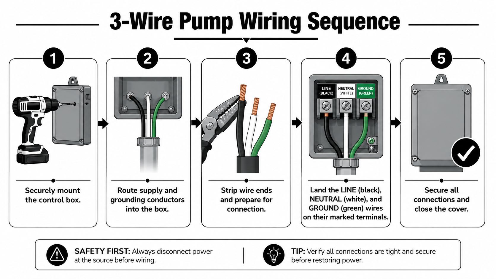
A 3-wire, single-phase submersible pump usually brings the control box into the job, and that changes the order of work. Start by identifying the equipment, then wire to the nameplate and terminal labels, not from memory. Mount the box where it stays dry and accessible, route the supply conductors and grounding conductor into it, then land the drop cable exactly as the manufacturer shows. If the labels and the motor nameplate disagree, stop and verify the pump and box together before you touch a screwdriver again.
Follow the terminal map, not memory
A manufacturer's wiring diagram for a 230V setup shows Yellow to Y, Red to R, and Black to B, and it also specifies that only copper wire belongs on the motor-to-supply connections (installation guide). That is the map to use while you work. Color codes, terminal lettering, and box layouts vary by equipment, so the field check is simple, match every conductor to the actual label in front of you before tightening anything.
Keep the conductor jacket intact as far into the enclosure as the strain relief allows, strip only what the terminal needs, and land each wire on the marked terminal. Tighten to the terminal block's specified torque and use copper only. If the conductor does not fit the lug properly, do not force it or stack strands under a screw that was not meant to take them.
Field habit that saves callbacks: Take a photo of the terminal layout before you close the cover. If a problem shows up later, you will know exactly what was landed where.
Know when the setup changes
A 2-wire pump lands as a simpler two-conductor arrangement and usually does not use a separate control box. A 3-phase system uses a different terminal pattern and needs a rotation check after startup. That second job is where a homeowner can get into trouble quickly, because a rotation mistake can make the pump run wrong or fail early. If the install turns into a 3-phase job, bring in a licensed electrician.
| 3-Wire Single-Phase Terminal Mapping at a Glance | ||
|---|---|---|
| Drop Cable Wire | Control Box Terminal | Function |
| Yellow | Y | Motor lead mapping |
| Red | R | Motor lead mapping |
| Black | B | Motor lead mapping |
Use the manufacturer's labels as the final authority, not a generic sketch copied from another box. If your control box uses different markings, follow that box and its installation guide. If you are checking the broader electrical grounding context while you work, talk to DLG Electrical about earthing. For a practical explanation of how ground-fault protection fits into a pump circuit, review this ground fault circuit interrupter overview.
Grounding, Bonding, and Code Basics
Grounding on a well pump is not a finishing touch. It is the part that gives fault current a path back to the source instead of leaving energized metal in the field where someone can touch it later. Land the ground conductor first, and leave enough slack so it stays connected if the cable gets tugged.
Grounding is not the same as “it's attached to metal”
The equipment grounding conductor is the green or bare wire that carries fault current back to the source. Bonding is the continuity between the enclosure, metallic conduit, and any other metal parts that could become energized. Both matter on a pump install, because one handles the fault path and the other keeps exposed metal at the same electrical potential.
For grounding requirements on submersible motor circuits, the control box or panel grounding terminal must be connected to the supply ground, and when metal conduit runs from the box to the supply panel, the grounding wire should be at least as large as the line conductors. That detail is part of safe practice, not paperwork, and it is one of the first things I check before I close a box. The same logic is why a homeowner should know whether the system has a real ground path or only a metal connection that looks convincing from the outside.
If you want a plain-language explanation of earthing and fault paths, talk to DLG Electrical about earthing. For the protection side of the circuit, ground-fault circuit interrupter basics explains how a GFCI fits into a pump system and why it reacts to stray current instead of waiting for a visible failure.
Test the system under load, not just at the panel
After the wiring is complete, verify zero voltage again, tug each lug lightly, then restore power at the panel and measure voltage at the controller line side with no load. After that, command the pump on through the float or pressure switch and measure voltage again at the motor terminals under load. That second reading tells you whether the system will behave in the field, because a circuit can look fine until the motor asks for current.
Measure under load, or you are only testing the easiest condition. A circuit can look fine at the panel and still sag badly at the motor.
The same approach applies when a megohmmeter is available, and it matters on 3-phase equipment during rotation checks as well. If the readings do not line up, the pump may be wired correctly and still fail because of supply quality, cable condition, or a component fault. A record label inside the box door with the date, voltage readings, and overload setting gives the next technician a solid baseline.
Troubleshooting the Common Field Failures
Most pump callbacks don't start with a neat terminal mistake. They start with a symptom. The pump hums, the overload trips, the pressure falls off, or the system cycles too often. That's why troubleshooting works better when you think in symptoms first and components second.
Match the symptom to the cheapest first check
If the pump hums but won't start, suspect a failed start capacitor, a seized motor, or low voltage under load. Start with the easiest checks, inspect the capacitor connections, confirm voltage at the box, then meter the motor if needed. If the motor is locked or the voltage collapses when it tries to start, stop before forcing repeated restarts.
If the pump starts then trips the overload, look at the run capacitor, friction at the pump end, or the wrong overload setting. A correctly wired box can still trip if the motor is being asked to do more than it should. That's why the overload reset button matters, and why a meter reading under load tells you more than a visual inspection ever will.
Don't confuse weak pressure with wiring success
A system that runs but makes weak pressure may have voltage drop, a worn pump, or a partial-phase loss on 3-phase equipment. The first check is often free, look for obvious leaks or tank issues, then move to voltage and current testing. The point is to avoid replacing parts before you know whether the electrical supply or the hydraulic side is the problem.
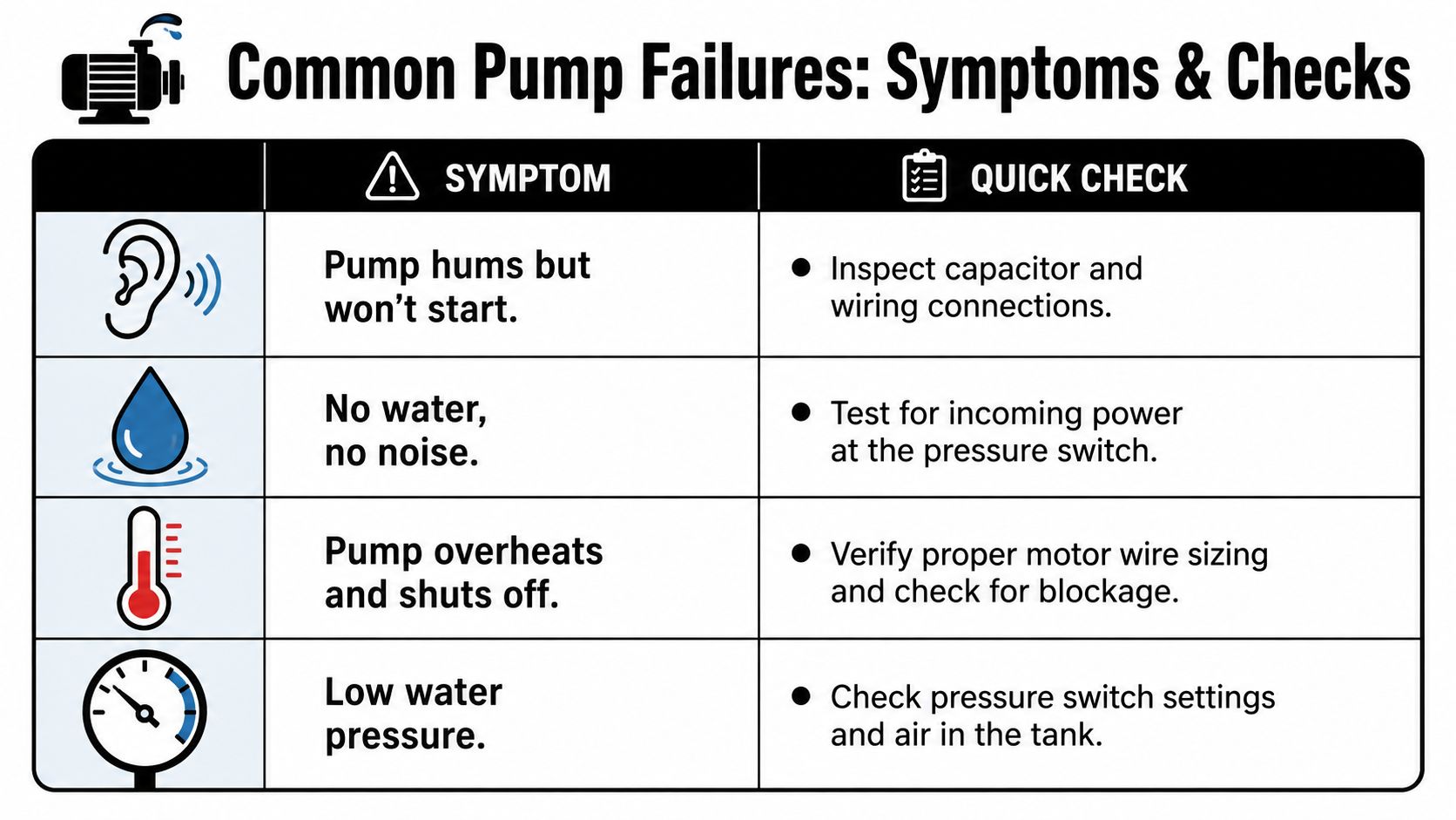
The tidy color match is the start of the diagnosis, not the end of it.
For a deeper look at current behavior as a diagnostic clue, the internal guide on Palm Beach electric motors is useful context when a pump still misbehaves after a clean wire job. If you want a framework for measuring motor behavior in the field, submersible pump motor current analysis is worth reading alongside your meter work. The important takeaway is simple, the problem may be in the capacitor, overload, voltage drop, or motor health, even when the terminals are perfect.
Permits, Code, and When to Call a Pro
A pump circuit isn't the place to guess your way through local rules. In Florida, a new electrical pump circuit can trigger an electrical permit, and a well-water connection can bring plumbing permit questions into the mix as well. Insurance carriers also like both permits on file when a claim gets reviewed, so the paper trail matters as much as the wire path.
Know where the DIY line sits
A careful homeowner can usually handle a 2-wire pump on a simple 240V circuit if the meter work is solid and the circuit is clearly identified. A 3-wire pump with a control box raises the stakes because the starting components are external and the box has to match the motor exactly. Any 3-phase work belongs with a licensed electrician, and commercial property installs should be commissioned by one too.
The same caution applies to the tank side of the system. If the pressure tank setup or switch logic is part of the job, step-by-step tank setup is a useful reference for understanding the mechanical side before electrical troubleshooting starts. Electrical and mechanical issues often show up together, so don't isolate the pump from the rest of the system in your head.
Use the right decision rule
If the job involves uncertain wire count, mismatched voltage, damaged insulation, repeated overload trips, or a box that doesn't match the motor nameplate, stop. Those are not “tighten one more screw” problems. They're identification and commissioning problems.
For help choosing a qualified pro, how to find a good electrician gives a practical standard for hiring someone who understands both code and field troubleshooting. The safest order of operations stays the same, identify the equipment, de-energize, match the box, wire copper only, ground properly, test under load, and document the readings. That sequence protects the homeowner, the pump, and the next technician who has to open the cover.
If you'd rather have a licensed team handle the control box, the wiring checks, and the load testing in one visit, Lighthouse Energy Services can do that work with the kind of field discipline that prevents repeat calls. Visit Lighthouse Energy Services to get help with submersible pump wiring, troubleshooting, and code-aware electrical service in Palm Beach County.